 dincer
hepguler robotics page01
dincer
hepguler robotics page01 dincer
hepguler robotics page01
dincer
hepguler robotics page01
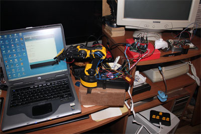
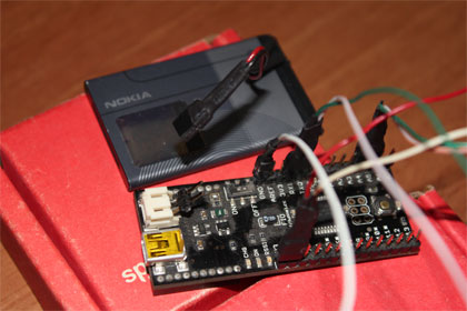
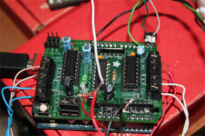
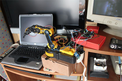
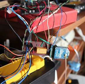
Always wanted to make a robotic arm which is remotely controlled by the help of a microprocessor. these gadgets are always pricey. in the end i found OWI 535 which is fairly good looking and inside my budget. i already had few Arduinos around and decided to make a robotic arm out of it. i began with making a motor controller using Adafruit motor shield. however it had only 4 motor controls. i needed a 5th controller for the gripper and added few electronics using a relay and a transistor to control the gripper motor. the task was not easy. i had to use an Arduino to move the arm and another Arduino clone which is a FIO to control the Nunchuck which i used as a wireless joystick. FIO has an X-Bee socket and can send controls wirelessly to the other Arduino which is controlling the arm. there is another X-Bee connected to this Arduino and they are communicating wirelessly... later i will place this robotic arm on my robotic rover to fetch things...
 |
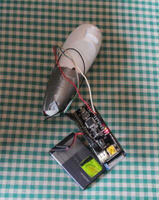
here you can see my OWI 535 Robotic arm and its components... an Arduino is moving the arm withs its internal power... controls are sent wirelessly by a Nunchuck connected to a FIO and x-bee powered by a cellphone battery... im using the Nunchuck joystick and its accelerometer to move the arm and its 2 buttons to control the gripper... | 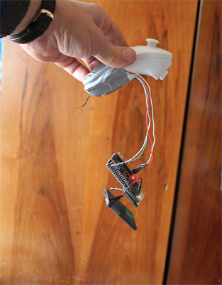 |
 |
 |
 |
 |
 |
 |
You can find a video of my robotic arm in action on YouTube HERE
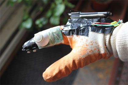 |
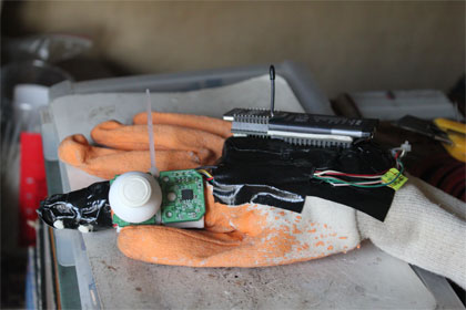
Update 2013: I made a wireless glove controller for my robotic arm... Now the arm is controlled by hand movements and the little thumb joystick of the nunchuck. I dismantled the nunchuck and mounted the electronics and the thumb joystick on a glove. the gripper is controlled via two buttons on one finger. ArduinoFio and X-Bee is mounted on a foam which is on the glove...
|
 |
I always wanted to make a robotic hand... For years it was one of my desires to make a robotic hand which is easy to build as DIY, but functional enough to use in many projects... There are many DIY robotic hands built by many talented designers and makers but none of the designs fulfilled my expectations. The hand must be easy to build but functional at the same time. At least it must hold and grab things and do that in a way our own hand does. One of the best DIY robotic hand designs belong to my friend Gael Langevin, who is a very talented designer, the InMoov Hand... This hand is part of the very well designed open-source 3d printable robot project, the InMoov. However, even this hand has some drawbacks according to me. It can grab things but the tendon mechanism to move fingers is controlled with fishing strings which is good for demonstrational purposes but lacks a firm grab. As an 3D graphics designer and a DIYer, I had to design something more versatile. The hand must be driven with steel wire tendons which are more suitable to apply more torque and control. The precision of movement can be controlled with servos but I have been testing some more alternatives such as worm gear or rack&pinion type of driving. The problem is that the mechanism must also be placed inside the hand housing without making the design too big and the hand must look like a real hand...
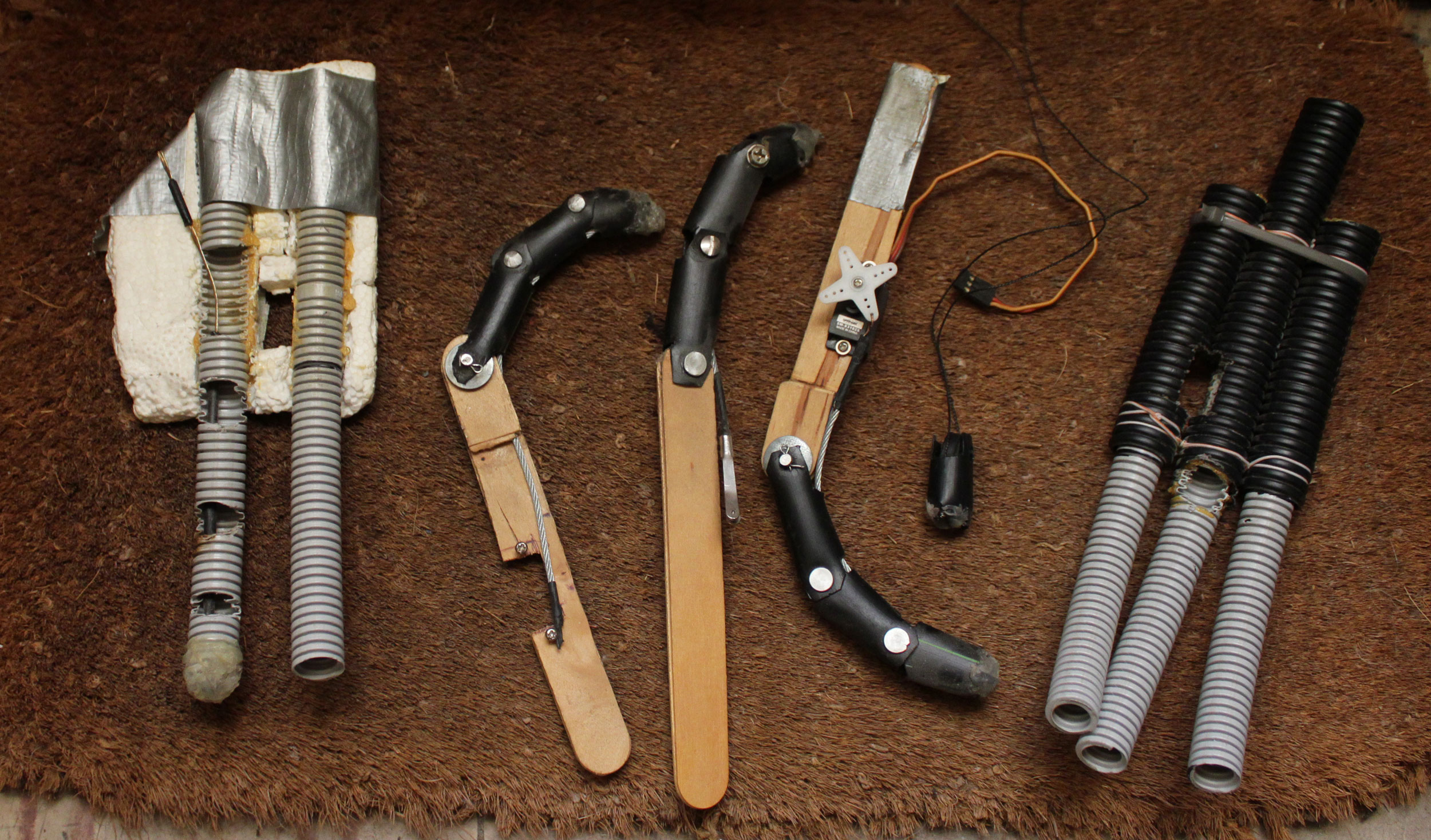
During all these years while I was busy with many other projects, I designed and tested many alternative hand elements. To find a sturdy and versatile design, I made many prototypes in the meantime. The flexible electrical wire holder pipes seem to be a good material and steel flexible wires are a good source of tendons. I learned a lot while making my own UAV airplane about servo driven movable parts and small accessories which I used while building wing ailerons and servo joints proved to be good gadgets to construct mechanisms for controlling finger movements... This photo shows many absurd trials and alternative designs for finger assemblies, finger joints, fingertips which I tested over years... But still I think that many other good alternatives are there, such as making use of springs, worm gears and rack&pinion type of designs...
|
 |
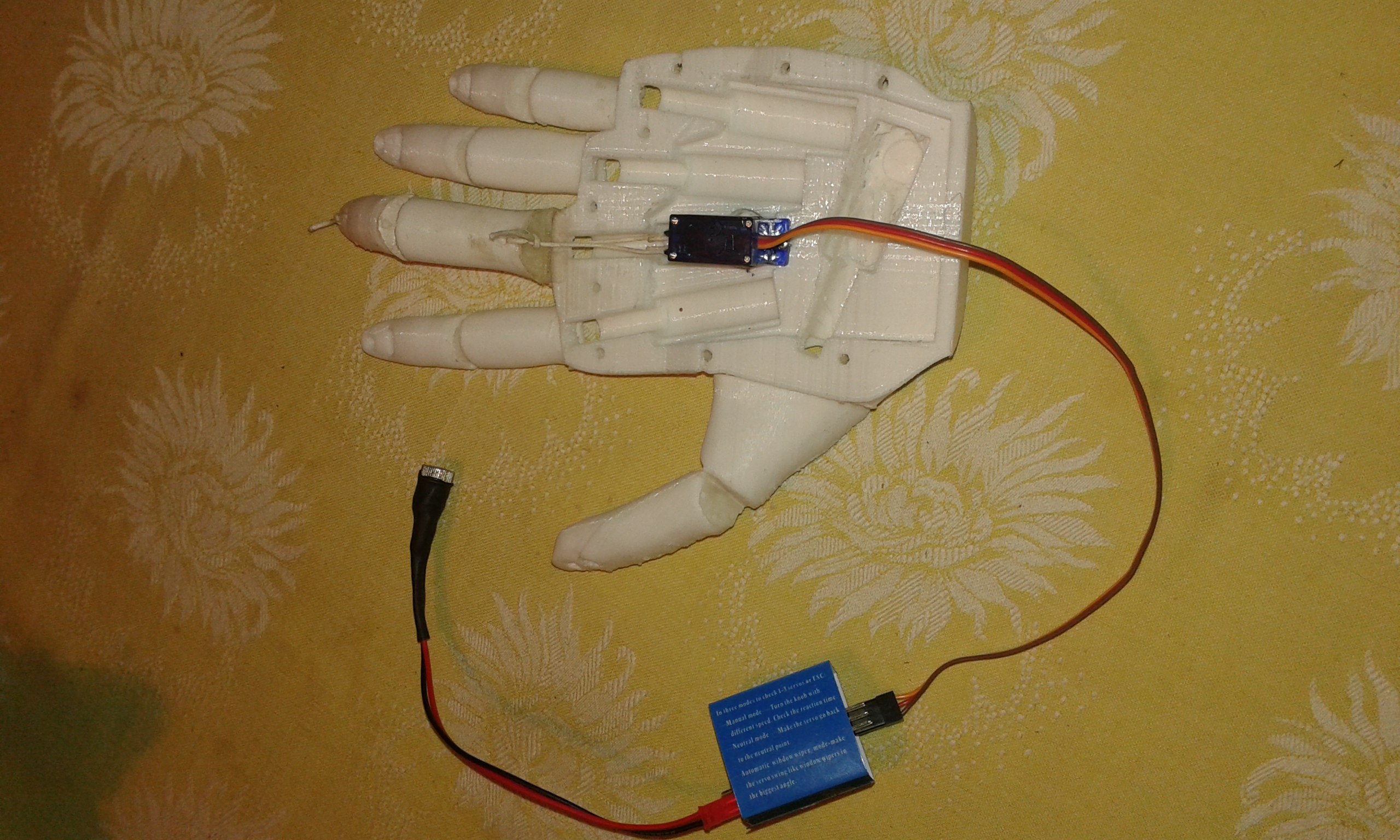
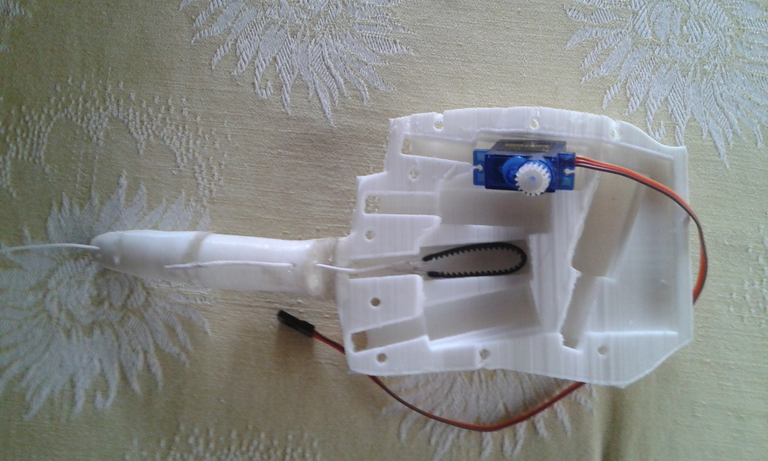
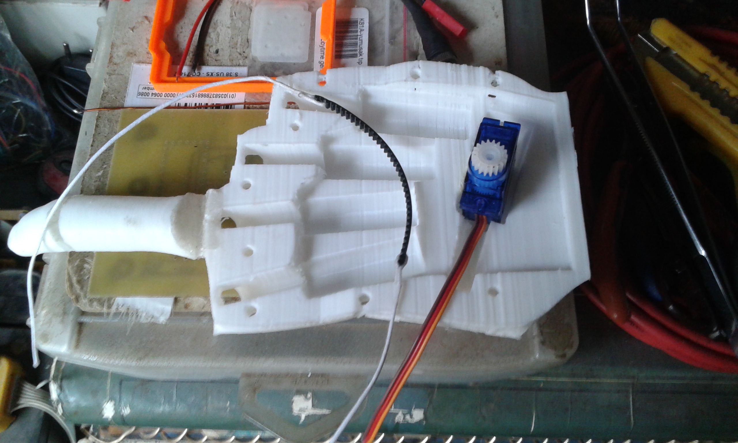
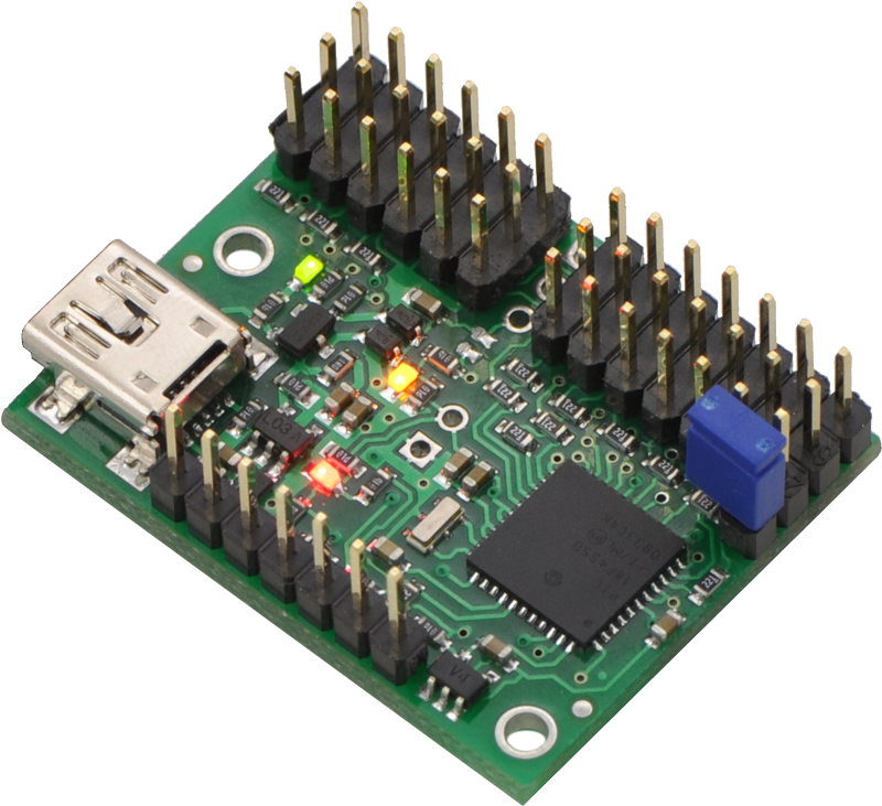
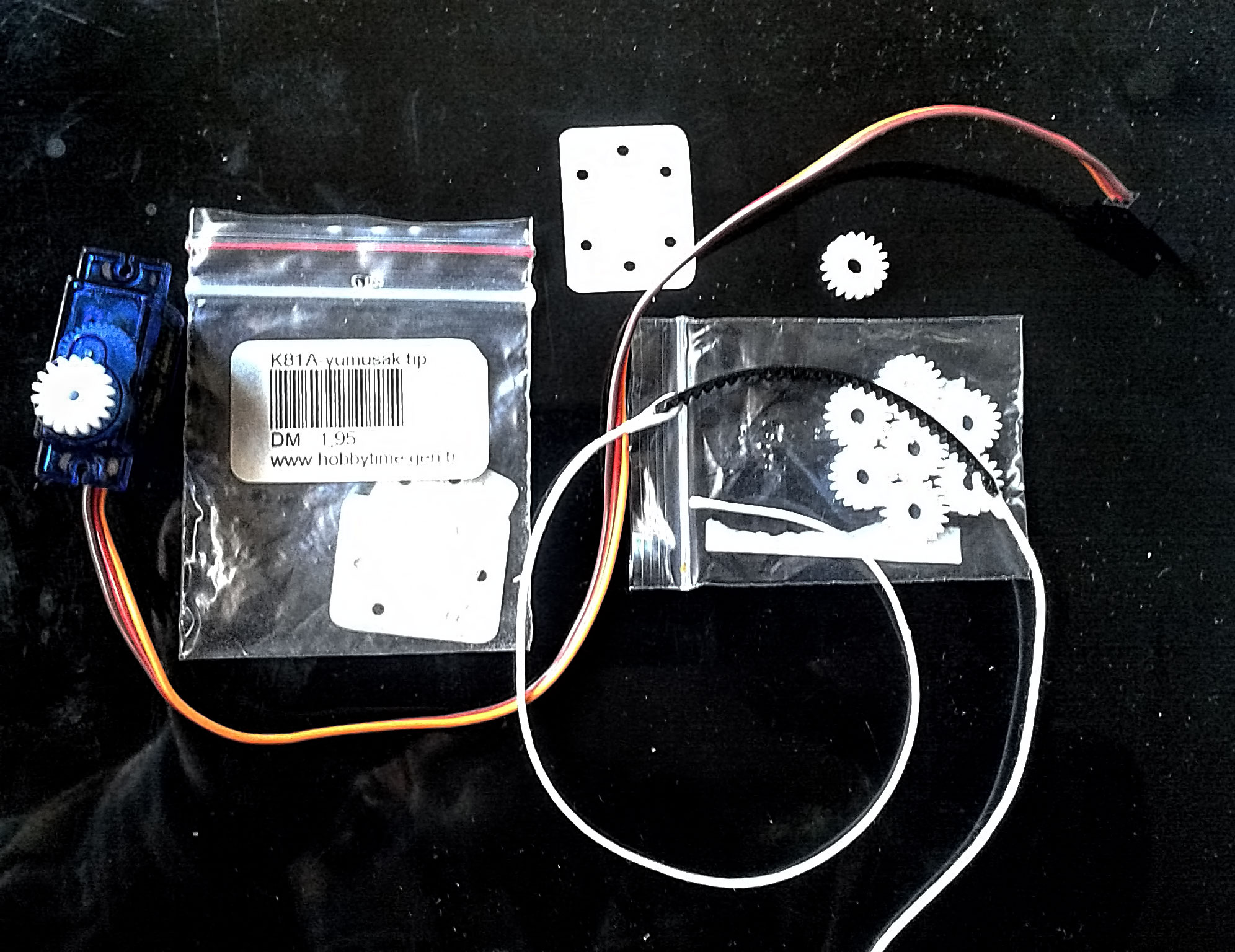
I think and work on my robotic hand from time to time. Recently I found this Ada hand, an open source robotic hand project from Open Bionics. Free 3d files are on Thingiverse and anyone can print it. The hand is designed to use tiny actuators for finger movements but these are too expensive and the tendons are only pulling fingers from one direction. I decided to improve this hand to be more real life, with more versatile tendons that actuate fingers in both directions equally to grab and hold things. There are many open source hand designs on the web but they are all using fishing lines to pull the fingers with some force to grab and when they release, no pull force is on the other side. Opening of the fingers also need some pulling from the back side. According to me this can only be achieved with internal servos. Some designs utilize servos but these are not inside the hand. Not realistic. I have to design a hand with internal servos pulling from both directions for a realistic grab and opening of fingers. I printed the hand and made some tests using specially prepared tendons. My tendons are composite structures with some strong and flexible rope connected at both sides of some 3mm GT2 timing belt. I also prepared 1cm diameter GT2 timing gears for my mini servos. These servos has around 2kg torque/cm which is well enough to grab and hold things. I regret that I should print the hand 10% bigger in all directions because even these small servos are hard to fit inside. After finishing up with the prototype I will print the actual hand 10% larger. While making the joints I used some flexible hinges which are used in model planes. These hinges are made with a paper like substance, very powerful and can not be ripped but very easily glued with super glue strongly. I also enforced the joints with some silicone sealant to be more flexible and strong. For testing purposes I am using a standard servo tester but later I will use different modules to control the hand. I am plannning to use Micro Maestro servo controller ( Pololu) to control the hand from my pc and also I have designed an Arduino Nano based microcontroller for the purpose. Both modules can comfortably fit inside the hand together with all the servos. |
|---|
 |
 |
 |
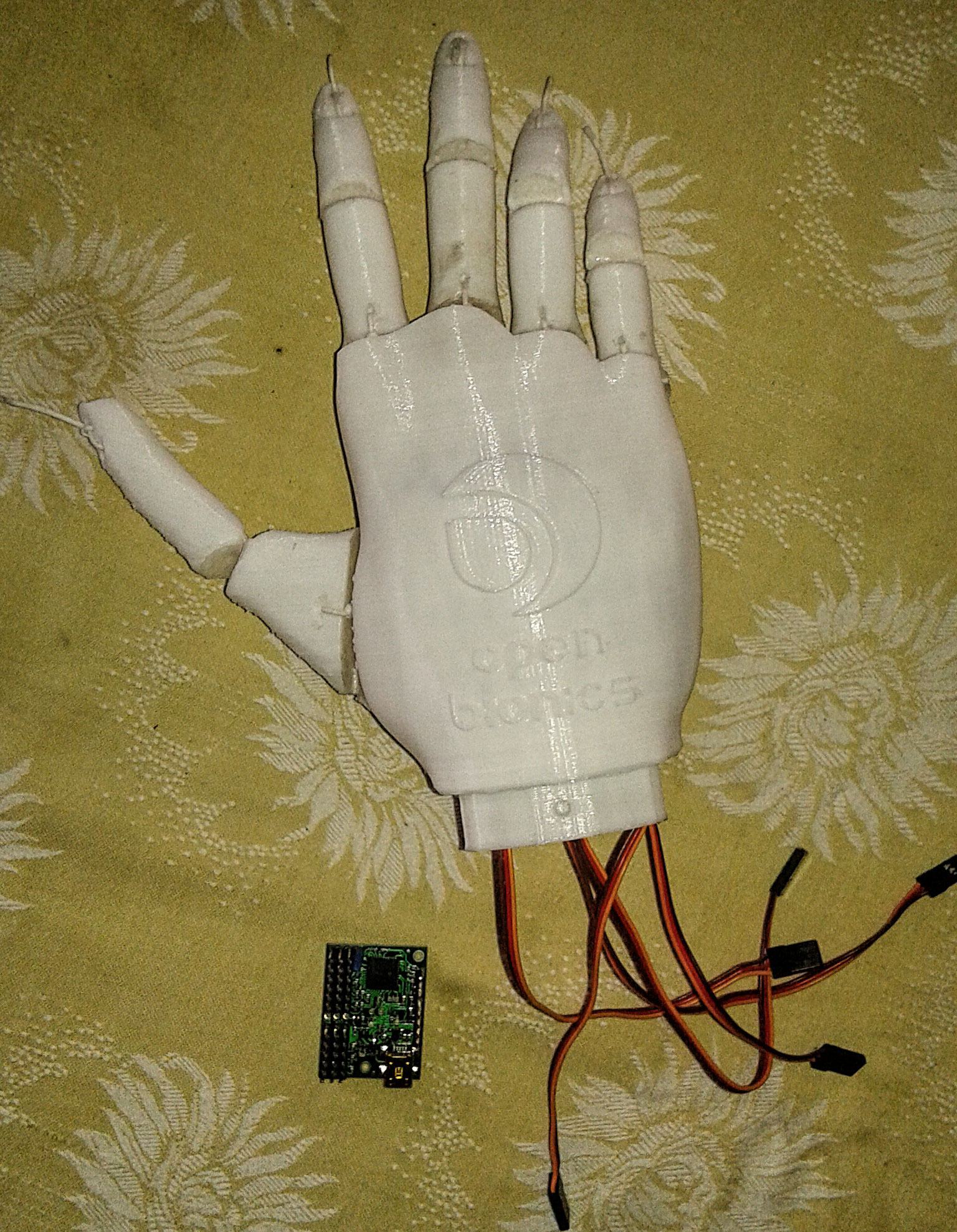 |
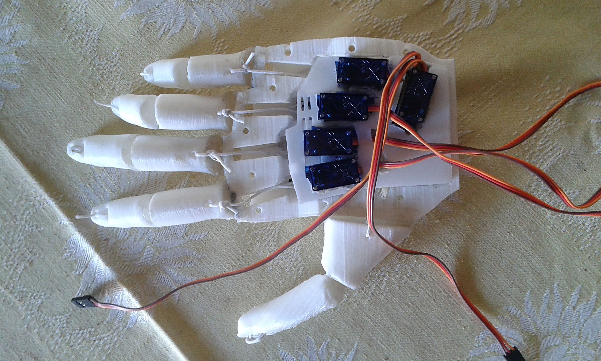
Some improvements on my robotic hand... I completed the inner activators (servos and tendons) and inner structure is stabilized with an inner plate holding the servos in place. The upper part closes nicely holding all inner components together. I am well pleased with the outcome. At this point I realized that the Mini Maestro controller does not fit inside for controlling the hand from my PC but its ok for the testing of finger movements. The actual hand will be controlled with an Arduino Mini which fits nicely inside the hand... | 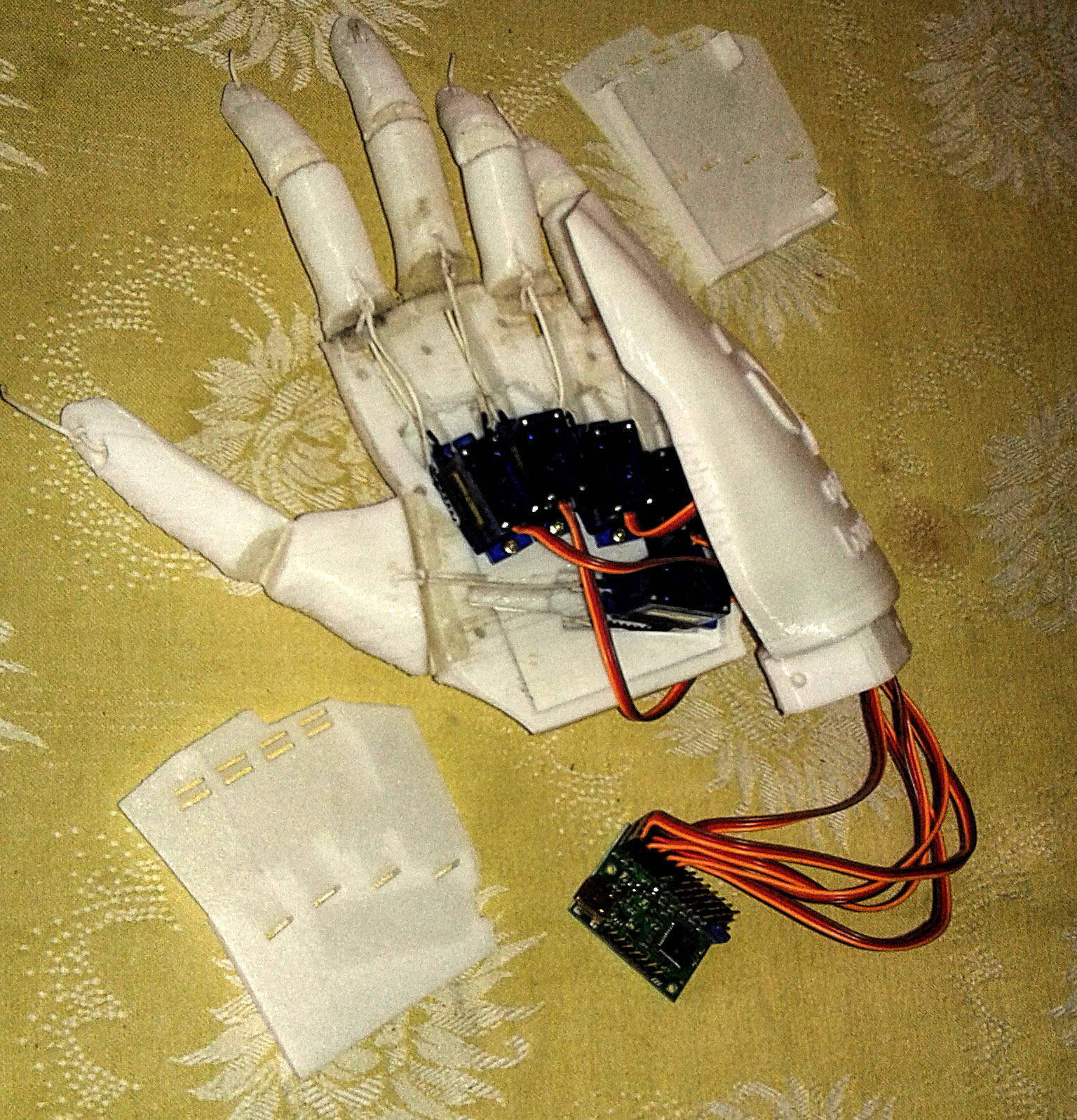 |
 |
 |
 |
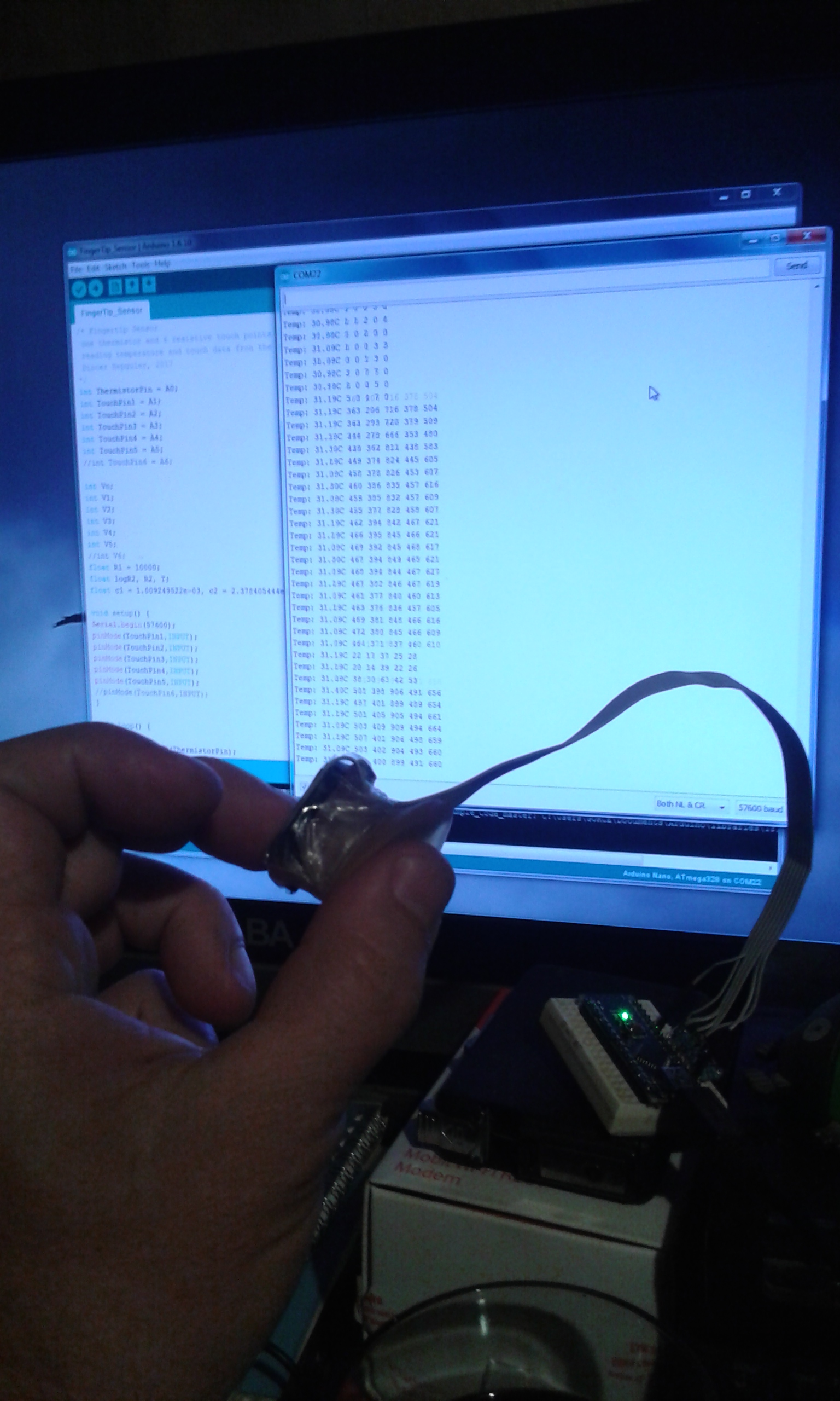 |
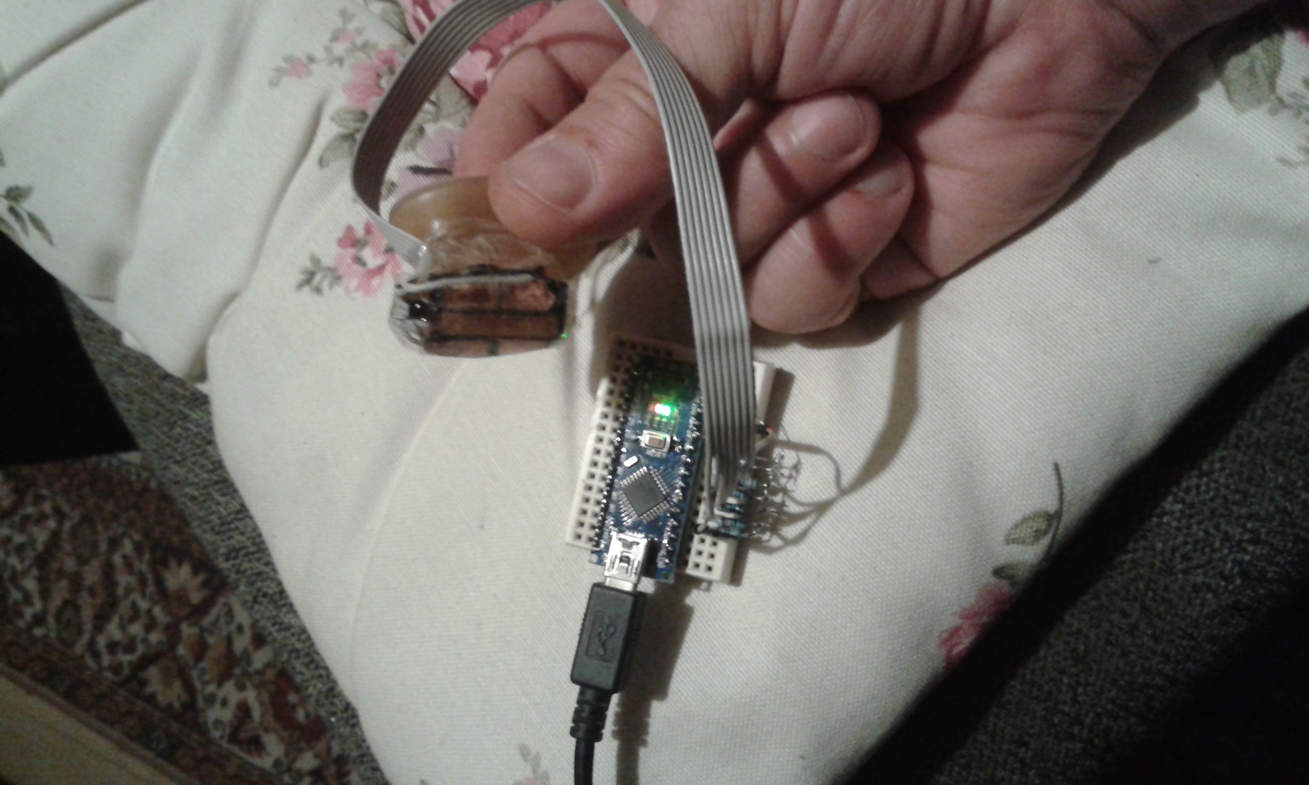
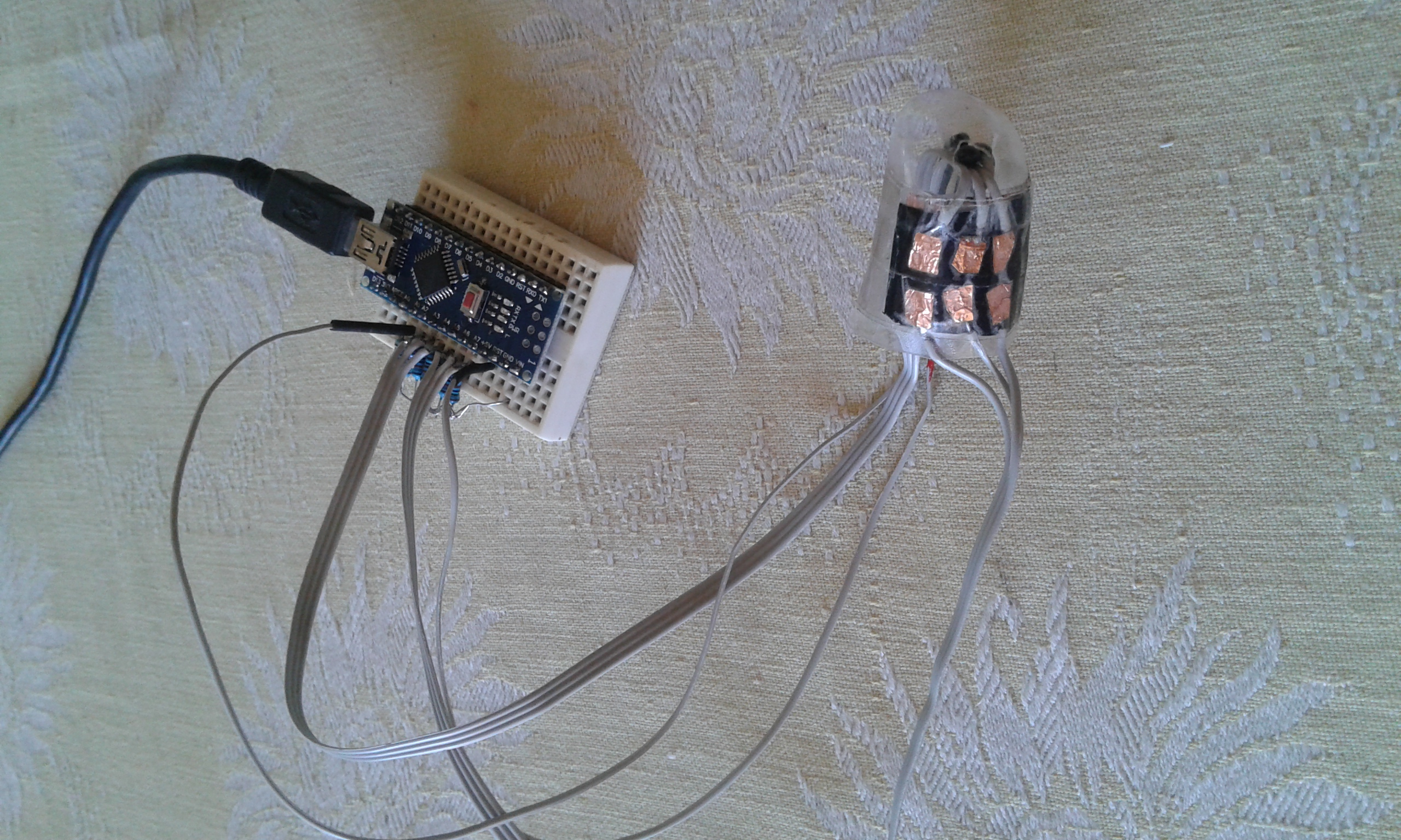
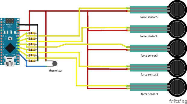
I decided to make a fingertip sensor for my robotic hand. this small sensor has 5 resistive touch sensors and one temp sensor. can easily be connected to any robotic hand. the temp sensor is selected as a NTC thermistor, because it is very small and sensitive to 2 decimal digits and 5 DIY resistive touch sensors made of double sided sticky tape, self adhesive copper sheet and Velostat. I am still working on it but as far as I can see it can detect the force of grab and type of grabbed material as rigid and soft. further study is needed with collected data... I updated my fingertip sensor after some tests... I realized that it performs better when placed on a soft flexible mount (just like in our fingers, skin over some flesh over the bones), some biomimetics worked well... I mounted my sensor on a silicon base and now its so sensitive and reactive... I used a small Arduino Nano to process the data. the resistors are 100K but I am planning to test the system with 1Megaohm ones for more sensitivity. The simple sketch is as follows: |
|
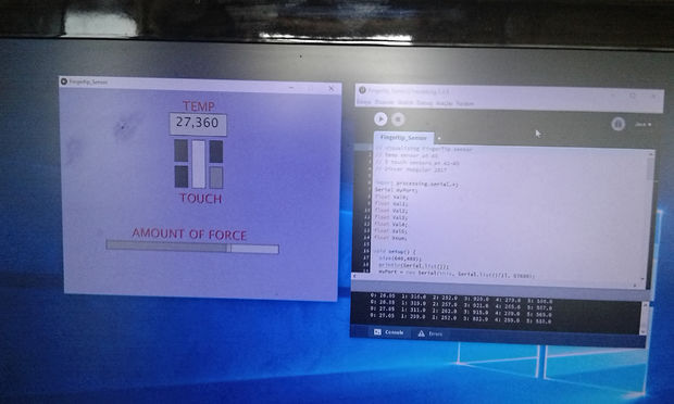
I wrote a Processing sketch to visualise the fingertip sensor data. by this you can see the temperature of the object in touch or environment, softness and hardness of the touched object and the amount of force exerted on it. this will enable to make some tests with the sensor. as far as I can see it is possible to detect the hardness of the touched object and you can control the force applied, which will make a robotic grabber to hold an egg without breaking it or dropping it...
|
|
|---|
Robotic Hand project will continue...
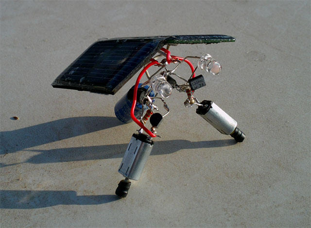 |
Right is one of my solar bugs... i love BEAM
robotics... this tiny solar robot uses the sun to move itself randomly
with its 2 motors... the solar cell provides energy which is stored in
the cap and transistors supplies this energy as bursts to the motors...
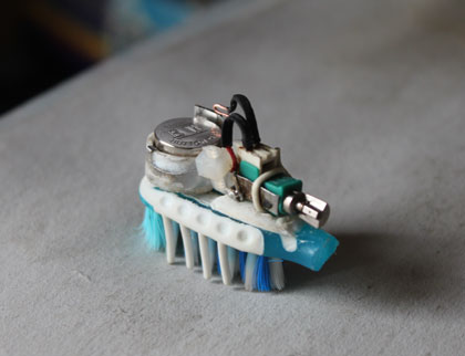
At left you see my little bristlebot... powered by a coin cell and a tiny pager motor, this bug moves around fast just like a real bug following contours of the surface... |
 |
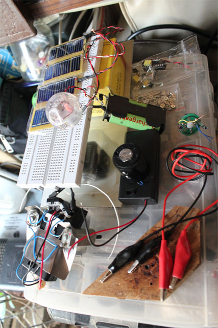 |
Left is my workbench showing my solar plantbot.
those solar cells will be the leaves powering the multicolor leds inside
the crystall ball which is the flower... at the lower left corner you
can also see my tiny bugbot which can wander around by itself using 2
motors and a 3v battery pack. the bugbot has 2 touch sensors in front
which it uses to sense the obstacles and change direction...
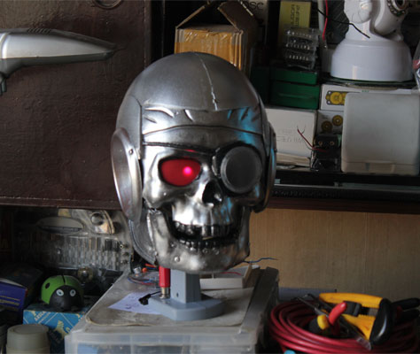
Right is my predator robotic head which can sense a person with its PIR sensor and can sweep its head from side to side when there is a human movement around. the red led on one of its eyes increases robotic appearance... I am planning to add 2 ears (sound sensors) and a camera in the future... |
 |
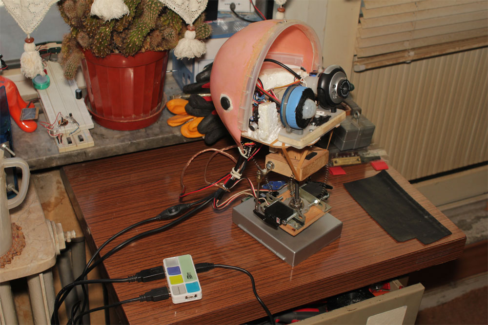 |
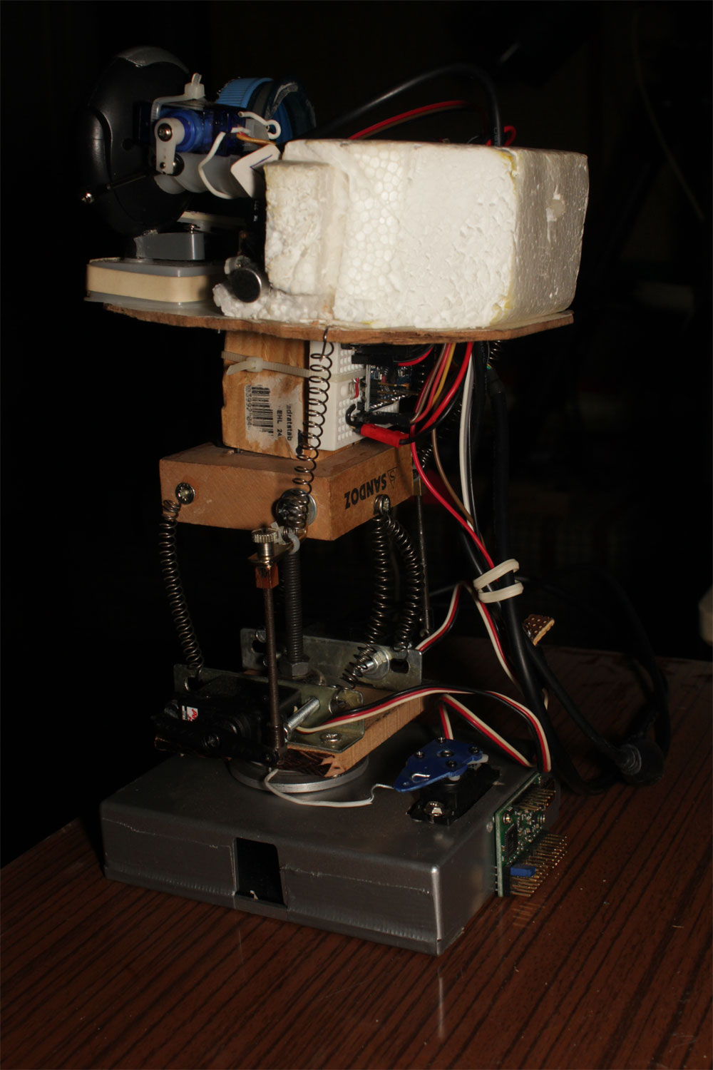
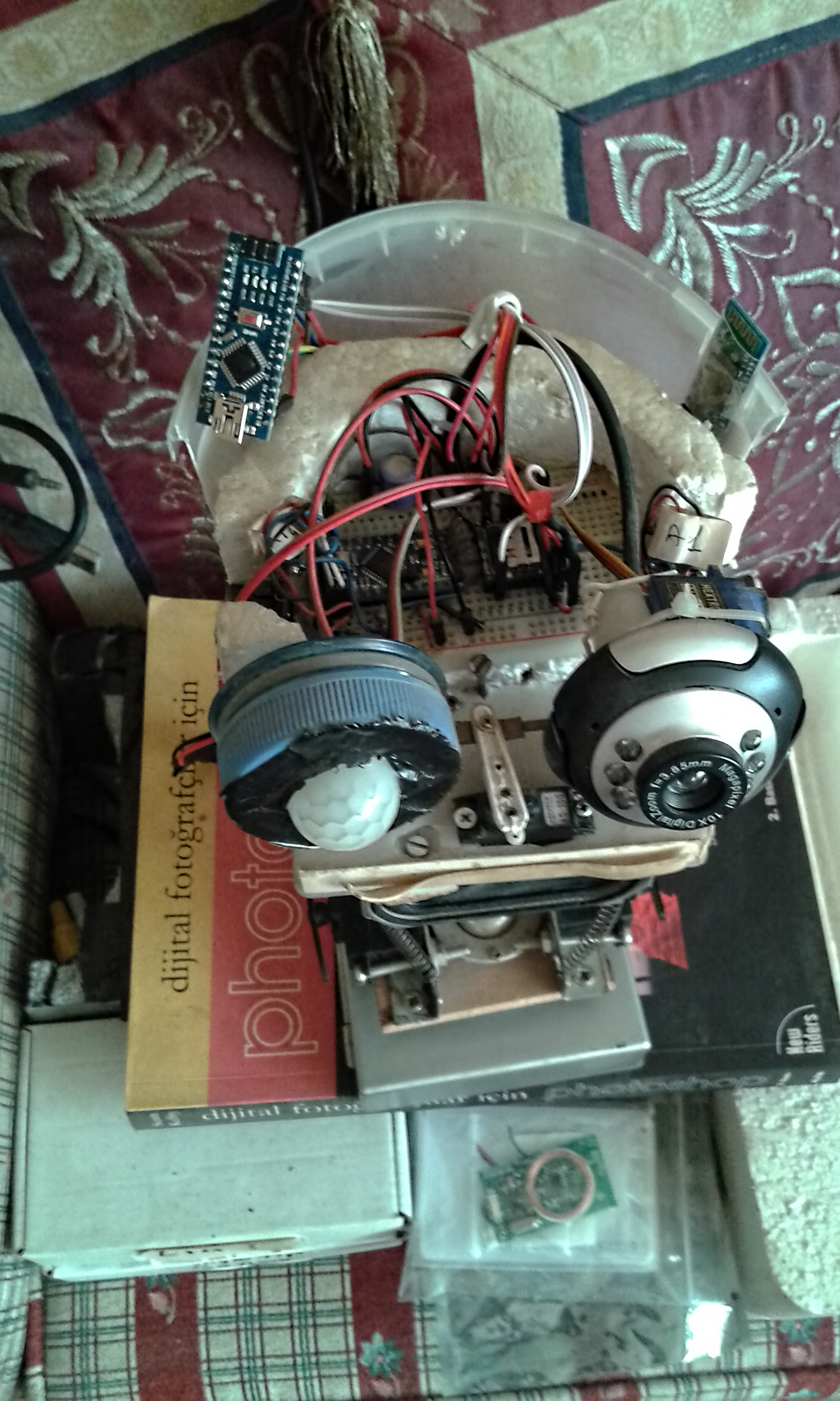
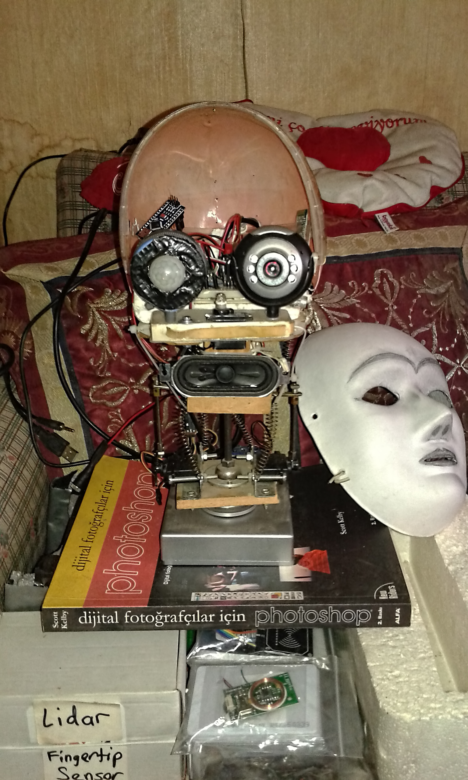
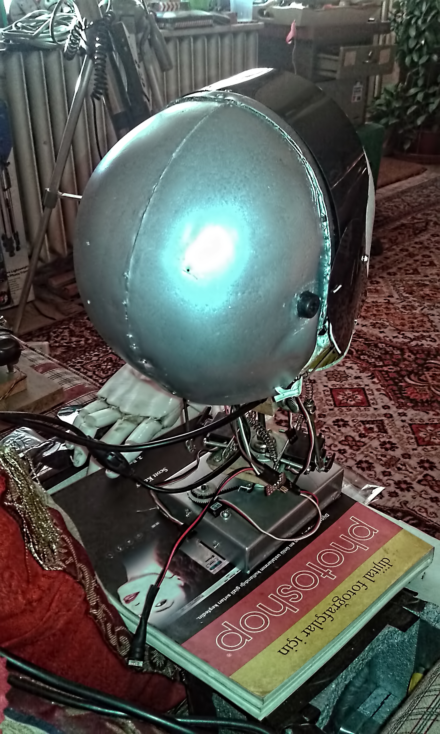
This is my other robotic head which is more complicated... It has a webcam as right eye and a PIR sensor as left eye. both eyes are controlled together with 2 servos. Neck mechanism consists of 3 servos which can make realistic movements. Robotic head is controlled with 2 Arduinos, one is responsible for computer vision software (OpenCV and MyRobotLab) and the other controls head&neck movements via servo controller (Pololu MicroMaestro). Head can detect human movement and can track faces... Update on Feb. 2018: I added bluetooth connectivity and by the help of an android app which can convert speech to text and send over serial (AMR Voice app), now I can make verbal communication with my robotic head. There are a long list of verbal communication set which she understands and responses with speech and movement. I added a 3rd Arduino Nano to the head for speech processing which controls a Wtv020-16 sound module for verbal responses... |
 |
 |
|---|
 |
 |
 |
|---|
please e-mail to me at dhepguler@hotmail.com